Equipment and Tools

Common HVAC Symbols and Their Meanings: A Complete Guide

A complete guide to common HVAC symbols, including ductwork, piping, control, equipment, and electrical symbols used in blueprints and schematics.

12 min readPublished January 1, 2026Updated July 14, 2026

Reading HVAC blueprints is like learning a new language filled with symbols, lines, and codes, each carrying important information about how a system operates. As an HVAC technician, apprentice, or system designer, you rely on these symbols to plan, install, and troubleshoot systems with accuracy.

In this guide we cover the most common HVAC symbols you need to know, including:

You’ll also learn practical tips for interpreting these symbols more effectively, like following logical flow paths and keeping a personal reference handy.

Now let’s crack the system and sharpen your blueprint-reading skills.

Part of the Equipment and Tools section in the HVAC Business Blog.
  • HVAC ductwork symbols

  • HVAC piping symbols

  • HVAC control symbols

  • HVAC equipment symbols

  • HVAC electrical symbols

What Are HVAC Symbols?

HVAC symbols are graphical symbols used in blueprints and schematics to represent the components and functions of heating, ventilation and air conditioning systems. These symbols include everything from ducts and valves to sensors and compressors.

Symbols allow you to quickly understand HVAC system layouts and connections without reading lengthy written descriptions. They also help you communicate effectively with other professionals working on the same project.

Let's take a closer look at why these visual elements matter.

Why Are HVAC Symbols Important?

Understanding HVAC symbols plays a critical role in system design, installation, and ongoing service work. If you can read and apply these symbols correctly, you reduce confusion and improve your job performance.

Here's why HVAC graphic representations matter:

Accurate installation depends on your ability to match symbols with the correct components and position them exactly where the design specifies, ensuring each part of the system functions as intended.

Efficient troubleshooting becomes possible when you can identify symbols representing valves, sensors, or flow paths. You save time by locating issues quickly and understanding how different elements interact within the system.

Reliable maintenance requires you to follow service diagrams precisely. Recognizing symbols helps you plan repairs, replace parts, and maintain system performance without guesswork.

Keep in mind that misreading symbols can lead to system malfunctions, incorrect installations, or missed connections. These mistakes often result in costly delays, rework, and safety issues that impact both schedules and customer satisfaction.

Now, let's walk through the most common HVAC symbols used in ductwork, piping, control systems, equipment layouts, and electrical schematics.

HVAC Ductwork Symbols

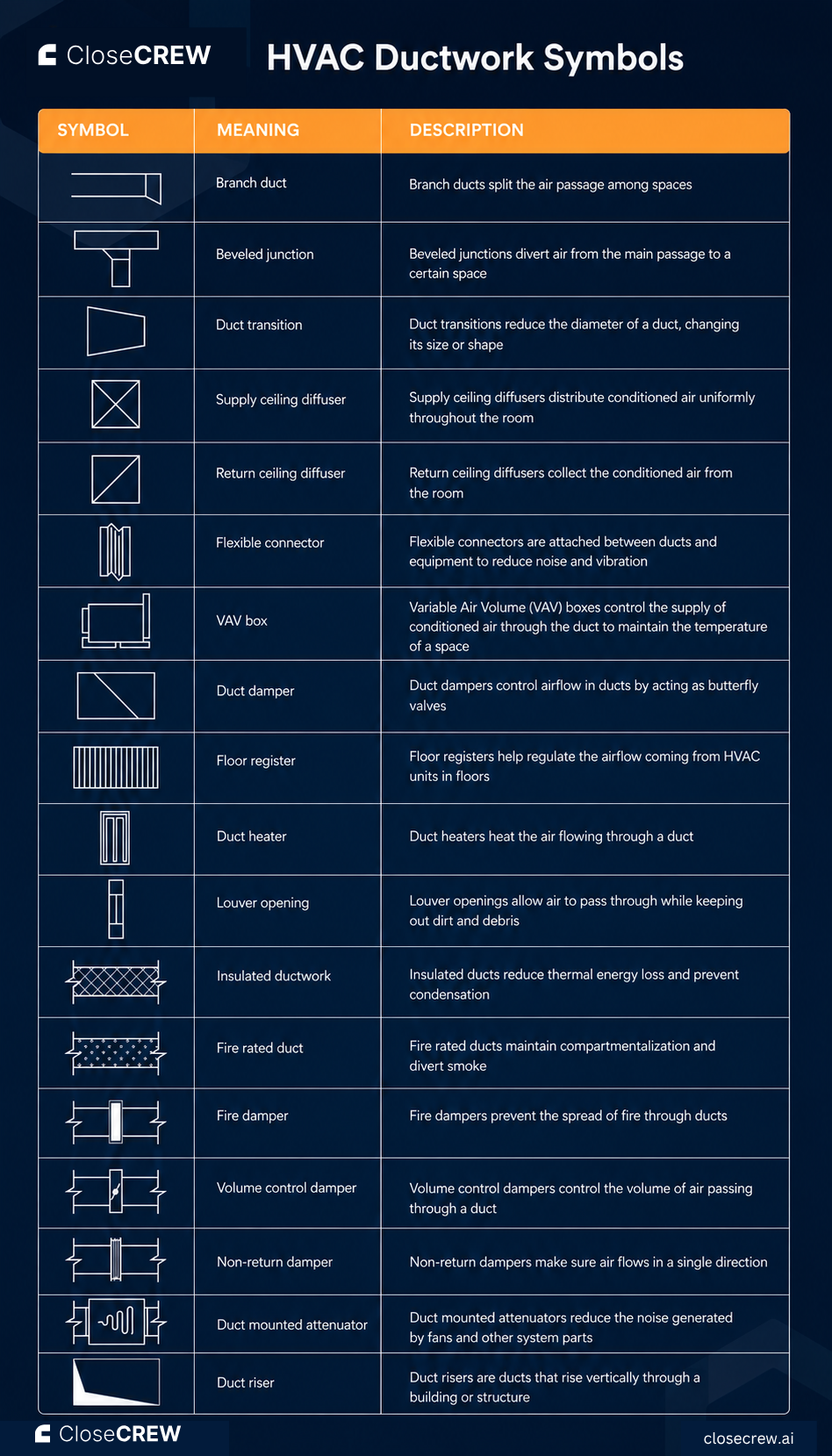
HVAC ductwork symbols represent the layout and components of air distribution systems, including supply ducts, return ducts, diffusers, and connections such as elbows or branch splits.

These graphic representations help you visualize airflow direction, system zones, and the physical routing of duct runs, so you can plan or inspect installations clearly.

Here are the key ductwork symbols and what they mean.

HVAC ductwork symbols chart showing branch ducts, diffusers, dampers, and related components

Common HVAC ductwork symbols and their meanings

Symbol

Meaning

Description

Branch duct

Branch duct

Branch ducts divide the air passage to distribute conditioned air among multiple spaces.

Beveled junction

Beveled junction

Beveled junctions redirect air from the main passage into a specific space or zone.

Duct transition

Duct transition

Duct transitions change the diameter of a duct, altering its size or shape to match different sections.

Supply ceiling diffuser

Supply ceiling diffuser

Supply ceiling diffusers spread conditioned air evenly throughout a room.

Return ceiling diffuser

Return ceiling diffuser

Return ceiling diffusers gather conditioned air from the room and channel it back into the system.

Flexible connector

Flexible connector

Flexible connectors attach between ducts and equipment to minimize noise and vibration.

VAV box

VAV box

Variable Air Volume (VAV) boxes regulate the supply of conditioned air through the duct to maintain room temperature.

Duct damper

Duct damper

Duct dampers manage airflow within ducts by functioning as butterfly valves.

Floor register

Floor register

Floor registers help control the airflow coming from HVAC units installed in floors.

Duct heater

Duct heater

Duct heaters warm the air as it flows through the ductwork.

Louver opening

Louver opening

Louver openings let air pass through while filtering out dirt and debris.

Insulated ductwork

Insulated ductwork

Insulated ducts minimize thermal energy loss and help prevent condensation.

Fire rated duct

Fire rated duct

Fire rated ducts preserve compartmentalization and redirect smoke in emergency situations.

Fire damper

Fire damper

Fire dampers stop the spread of fire through duct systems.

Volume control damper

Volume control damper

Volume control dampers regulate the amount of air passing through a duct.

Non-return damper

Non-return damper

Non-return dampers ensure air travels in only one direction.

Duct mounted attenuator

Duct mounted attenuator

Duct mounted attenuators reduce noise created by fans and other system components.

Duct riser

Duct riser

Duct risers are vertical ducts that rise through a building or structure.

HVAC Piping Symbols

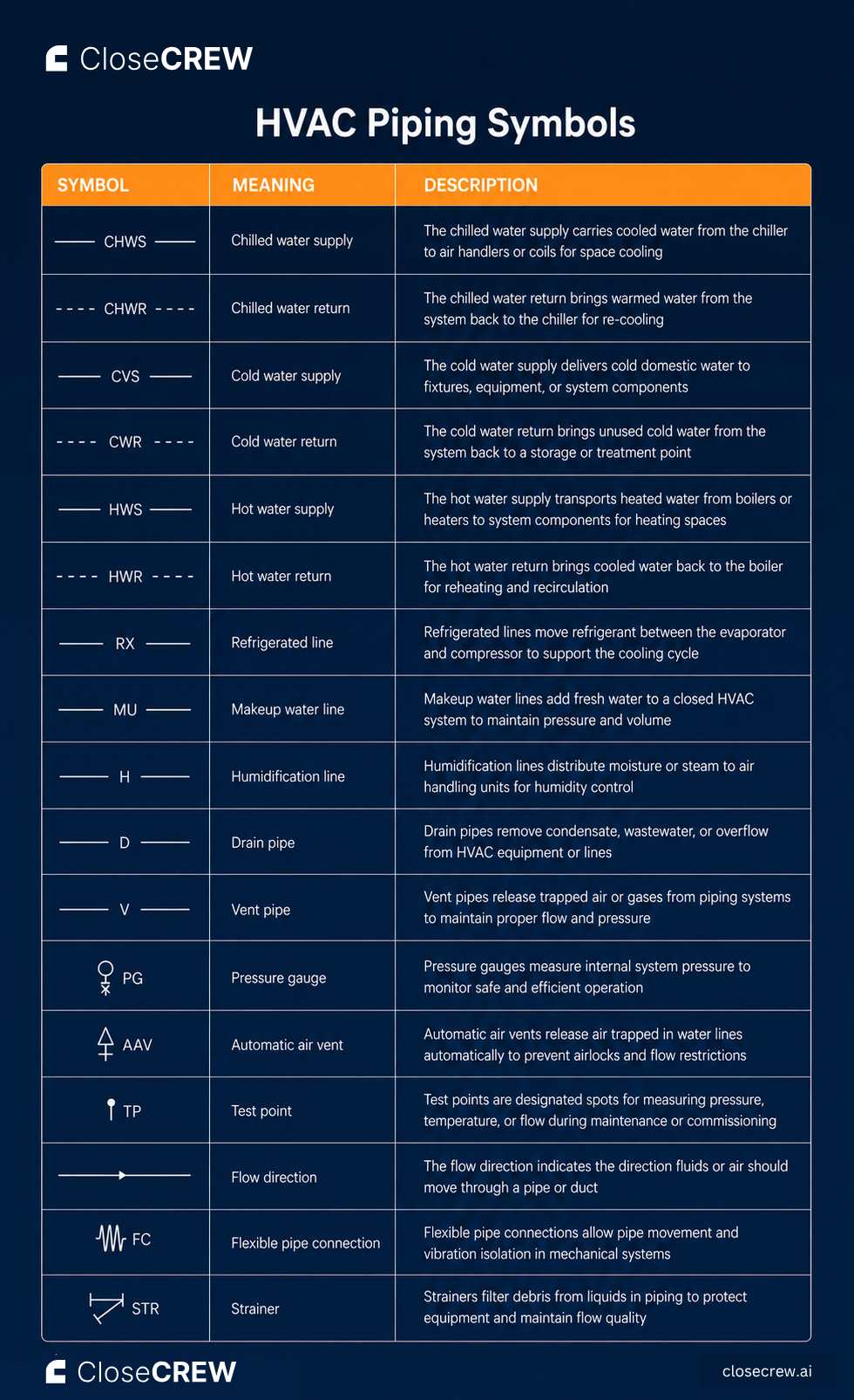
HVAC piping symbols are used to map the movement of fluids such as chilled water, hot water, or refrigerant through the system.

These symbols are particularly useful when working with boilers, pumps, and cooling towers, as they indicate flow direction, pipe size, and connections like valves or gauges.

Here are commonly used piping symbols and their functions.

HVAC equipment symbols chart showing chillers, air handlers, pumps, and compressors

Common HVAC piping symbols and their meanings

Symbol

Meaning

Description

CHWS

Chilled water supply

Carries cooled water from the chiller to air handlers or coils for space cooling.

CHWR

Chilled water return

Returns warmed water from the system back to the chiller for re-cooling.

CVS

Cold water supply

Delivers cold domestic water to fixtures, equipment, or system components.

CWR

Cold water return

Returns unused cold water from the system back to a storage or treatment point.

HWS

Hot water supply

Transports heated water from boilers or heaters to system components for space heating.

HWR

Hot water return

Returns cooled water back to the boiler for reheating and recirculation.

RX

Refrigerated line

Moves refrigerant between the evaporator and compressor to support the cooling cycle.

MU

Makeup water line

Adds fresh water to a closed HVAC system to maintain pressure and volume.

H

Humidification line

Distributes moisture or steam to air handling units for humidity control.

D

Drain pipe

Removes condensate, wastewater, or overflow from HVAC equipment or lines.

V

Vent pipe

Releases trapped air or gases from piping systems to maintain proper flow and pressure.

PG

Pressure gauge

Measures internal system pressure to monitor safe and efficient operation.

AAV

Automatic air vent

Releases air trapped in water lines automatically to prevent airlocks and flow restrictions.

TP

Test point

Designated spots for measuring pressure, temperature, or flow during maintenance or commissioning.

Flow direction

Flow direction

Indicates the direction fluids or air should move through a pipe or duct.

FC

Flexible pipe connection

Allows pipe movement and vibration isolation in mechanical systems.

STR

Strainer

Filters debris from liquids in piping to protect equipment and maintain flow quality.

HVAC Control Symbols

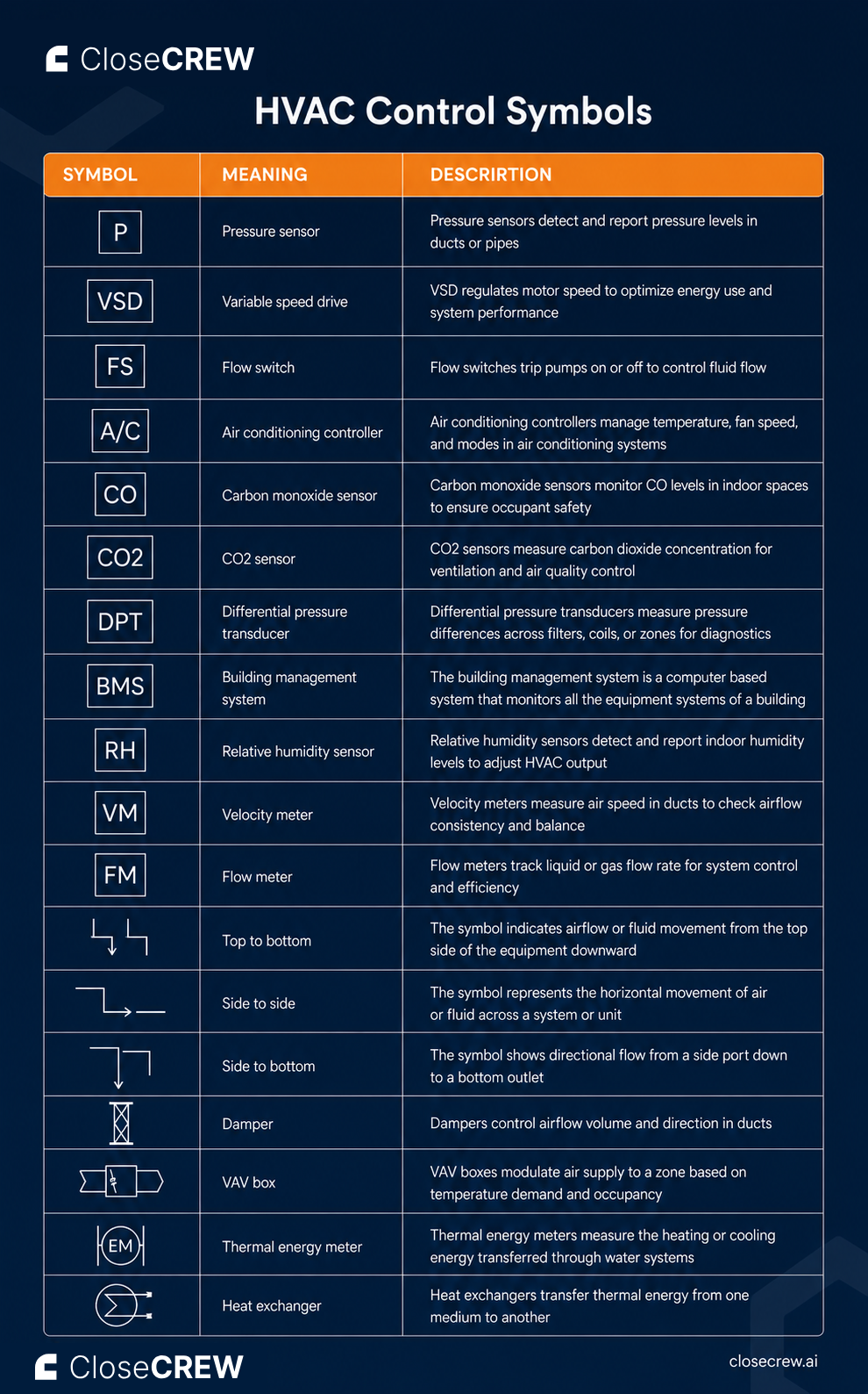
HVAC control symbols indicate sensors, actuators, switches, and controllers that regulate the system's performance.

These visual elements show how temperature, pressure, and airflow are monitored and adjusted, either automatically or manually.

The table below covers key control symbols and their uses.

HVAC electrical symbols chart showing transformers, switches, capacitors, and wiring connections

Common HVAC control symbols and their meanings

Symbol

Meaning

Description

P

Pressure sensor

Detects and reports pressure levels in ducts or pipes.

VSD

Variable speed drive

Regulates motor speed to optimize energy use and system performance.

FS

Flow switch

Trips pumps on or off to control fluid flow.

A/C

Air conditioning controller

Manages temperature, fan speed, and modes in AC systems.

CO

Carbon monoxide sensor

Monitors CO levels in indoor spaces to ensure occupant safety.

CO2

CO2 sensor

Measures carbon dioxide concentration for ventilation and air quality control.

DPT

Differential pressure transducer

Measures pressure differences across filters, coils, or zones for diagnostics.

BMS

Building management system

A computer-based system that monitors all equipment systems within a building.

RH

Relative humidity sensor

Detects and reports indoor humidity levels to adjust HVAC output.

VM

Velocity meter

Measures air speed in ducts to check airflow consistency and balance.

FM

Flow meter

Tracks liquid or gas flow rate for system control and efficiency.

Damper

Damper

Controls airflow volume and direction in ducts.

VAV box

VAV box

Modulates air supply to a zone based on temperature demand and occupancy.

EM

Thermal energy meter

Measures the heating or cooling energy transferred through water systems.

Heat exchanger

Heat exchanger

Transmits thermal energy from one medium to another.

HVAC Equipment Symbols

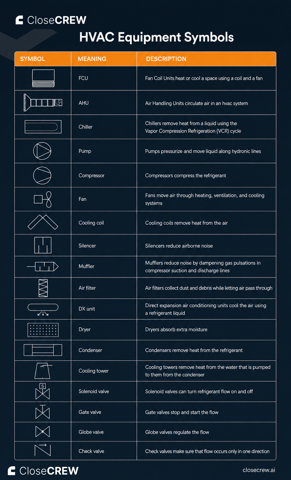
HVAC equipment symbols represent the major mechanical units in a system, such as chillers, air handling units, furnaces, compressors, and fans.

These visual elements allow you to identify the type and function of each piece of equipment without needing a photo or model number. Recognizing them quickly helps you plan layouts, manage installations, and verify equipment placement on drawings.

Here are the most frequently used equipment symbols and their meanings.

Common HVAC equipment symbols and their meanings

HVAC piping symbols chart showing chilled water, hot water, refrigerant, and drain lines

Symbol

Meaning

Description

FCU

Fan Coil Unit

Heats or cools a space using a coil and a fan.

AHU

Air Handling Unit

Circulates air throughout an HVAC system.

Chiller

Chiller

Removes heat from a liquid using the Vapor Compression Refrigeration (VCR) cycle.

Pump

Pump

Pressurizes and moves liquid along hydronic lines.

Compressor

Compressor

Compresses the refrigerant within the cooling system.

Fan

Fan

Moves air through heating, ventilation, and cooling systems.

Cooling coil

Cooling coil

Removes heat from the air passing through it.

Silencer

Silencer

Reduces airborne noise within the system.

Muffler

Muffler

Reduces noise by dampening gas pulsations in compressor suction and discharge lines.

Air filter

Air filter

Collects dust and debris while allowing air to pass through.

DX unit

DX unit

Direct expansion AC units cool air using a refrigerant liquid.

Dryer

Dryer

Absorbs excess moisture from the system.

Condenser

Condenser

Removes heat from the refrigerant.

Cooling tower

Cooling tower

Removes heat from water pumped from the condenser.

Solenoid valve

Solenoid valve

Turns refrigerant flow on and off.

Gate valve

Gate valve

Stops and starts flow within the system.

Globe valve

Globe valve

Regulates flow within the system.

Check valve

Check valve

Ensures flow occurs in only one direction.

HVAC Electrical Symbols

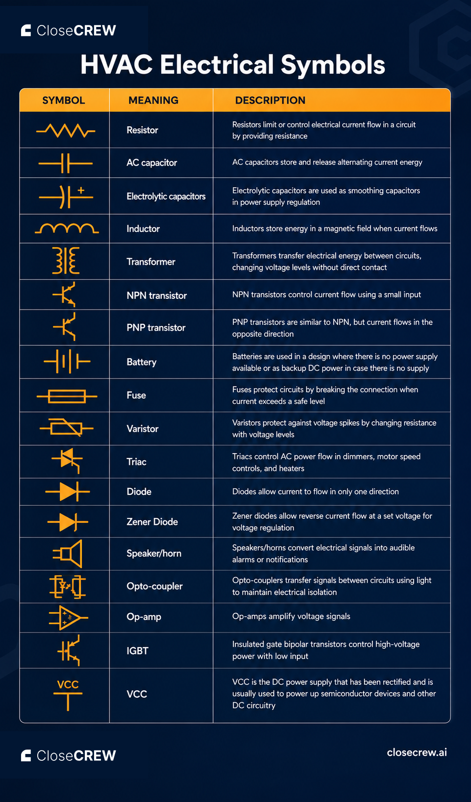
HVAC electrical symbols represent the electrical components and circuits that power and control heating, cooling, and ventilation systems.

Symbols for transformers, resistors, capacitors, switches, and wiring connections help you follow the electrical design safely and accurately.

Below is a reference list of common electrical symbols and their definitions.

Common HVAC electrical symbols and their meanings

HVAC control symbols chart showing sensors, actuators, and building management components

Symbol

Meaning

Description

Resistor

Resistor

Limits or controls electrical current flow in a circuit by providing resistance.

AC capacitor

AC capacitor

Stores and releases alternating current energy.

Electrolytic capacitor

Electrolytic capacitor

Used as smoothing capacitors in power supply regulation.

Inductor

Inductor

Keeps energy in a magnetic field when current flows through it.

Transformer

Transformer

Transfers electrical energy between circuits, changing voltage levels without direct contact.

NPN transistor

NPN transistor

Controls current flow using a small input signal.

PNP transistor

PNP transistor

Similar to NPN but current flows in the opposite direction.

Battery

Battery

Provides DC power where no main supply is available or as backup.

Fuse

Fuse

Protects circuits by breaking the connection when current exceeds a safe level.

Varistor

Varistor

Protects against voltage spikes by changing resistance with voltage levels.

Triac

Triac

Controls AC power flow in dimmers, motor speed controls, and heaters.

Diode

Diode

Allows one-way current flow.

Zener diode

Zener diode

Allows reverse current flow at a set voltage for voltage regulation.

Speaker/horn

Speaker/horn

Converts electrical signals into audible alarms or notifications.

Opto-coupler

Opto-coupler

Transfers signals between circuits using light to maintain electrical isolation.

Op-amp

Op-amp

Amplifies voltage signals within the circuit.

IGBT

IGBT

Insulated gate bipolar transistors control high-voltage power with low input.

VCC

VCC

The DC power supply that has been rectified, used to power semiconductor devices and DC circuitry.

Tips for Reading and Interpreting HVAC Schematics

Reading HVAC schematics effectively requires a clear process and the right habits to avoid mistakes and speed up your workflow.

Here are some tips to help you interpret drawings with more precision and confidence:

1: Use the Legend or Key

Before analyzing any schematic, review the legend or symbol key provided in the plan set. Since different engineers or projects may use slightly different symbols, this step ensures you interpret each component correctly from the start.

2: Identify the Main Components First

Locate the core pieces of equipment, such as chillers, air handling units, or control panels, before tracing secondary lines or devices. This top-down approach gives you a clear system overview and makes the connections easier to follow.

3: Trace Connections in Logical Order

Follow each system's flow step by step, starting from the source and moving through distribution to the endpoints. This approach helps you understand how energy or air moves through the system and allows you to catch missing or misaligned components.

4: Keep a Mobile App or Personal Reference Sheet

Maintain a quick-access tool with commonly used symbols and notes to save time and build confidence over time. Digital reference apps on your phone make it easy to look up symbols while you're on the job site.

5: Ask Questions When You're Confused

If a symbol looks unfamiliar or a connection seems unclear, ask a senior technician, engineer, or supervisor. Getting clarification early prevents costly rework or system failures down the line.

6: Use Highlighters or Digital Markup Tools

Mark your printouts or digital files to track areas you've reviewed or completed. Color coding helps you visualize the system's layout and spot potential issues faster during installation or troubleshooting.

How CloseCrew Supports HVAC Technicians and Business Owners

Understanding HVAC symbols and schematics makes your technicians better at their jobs. But even the most skilled tech can't generate revenue from a call that goes unanswered or a lead that falls through the cracks.

CloseCrew gives your HVAC business an AI Employee named Larry who handles the operational side so your technicians can focus on what they do best: expert installation, diagnostics, and repair.

Larry answers every call 24/7. When your SEO, Google Ads, or referrals drive a homeowner to call, whether it's 2 PM or 11 PM, Larry picks up, qualifies the need, and books the job directly into your FSM calendar.

Larry handles every channel. Calls, texts, webchats, third-party leads, and email all flow into a single centralized inbox accessible to Larry and your entire team.

Larry keeps your calendar full. CloseCrew's AI marketing tools proactively manage maintenance agreement renewals, unsold estimate follow-ups, and seasonal re-engagement campaigns so your techs stay productive year-round.

Larry automates your reputation. Personalized review requests are sent automatically after every completed job, building your Google reviews on autopilot and boosting local search rankings.

HVAC businesses using CloseCrew report:

Results HVAC businesses are seeing with CloseCrew

Business

Result

Warner Super Service

57 appointments set by Larry in 30 days

Top Mechanical Service Inc.

$40K saved annually with Voice AI

Heritage Mountain Heating & Cooling

41 additional appointments in 30 days

Air Texas

$2,000/month saved replacing their answering service

Air Design Heating & Cooling

5-15 hours saved weekly on admin

Conclusion

Mastering HVAC symbols gives you a clear advantage in system design, installation, and maintenance.

Now that you recognize what each symbol means and how it fits into a schematic, you can reduce errors, speed up your work, and improve communication with your team.

Combine this knowledge with CloseCrew's full range of features and take your HVAC business to new heights.

Watch a demo and see how CloseCrew helps HVAC businesses grow revenue by 30% without adding headcount: https://closecrew.ai/

Trusted by 9,000+ home service businesses. White-glove onboarding in 48 hours. 200+ integrations with the tools your team already uses.

Frequently asked questions

What are HVAC symbols?

HVAC symbols are graphical symbols used in blueprints and schematics to represent heating, ventilation, and air conditioning components such as ducts, valves, sensors, compressors, fans, and electrical parts.

HVAC symbols help technicians, apprentices, designers, and installers understand system layouts, follow flow paths, install components correctly, troubleshoot faster, and communicate clearly with other professionals.

Common HVAC ductwork symbols include branch ducts, duct transitions, supply ceiling diffusers, return ceiling diffusers, flexible connectors, VAV boxes, duct dampers, floor registers, fire dampers, and duct risers.

Common HVAC piping symbols include CHWS for chilled water supply, CHWR for chilled water return, HWS for hot water supply, HWR for hot water return, RX for refrigerant line, PG for pressure gauge, AAV for automatic air vent, and STR for strainer.

HVAC technicians can read schematics better by reviewing the legend first, identifying main components, tracing connections in logical order, keeping a reference sheet, asking questions when confused, and using markup tools to track reviewed areas.

Related tools

Run the numbers before you update your price book or field software.

Free HVAC Templates

Invoices, estimates, maintenance agreements, and flat-rate pricing sheets for heating and cooling contractors.

Browse HVAC templates

Contractor Blog

Cross-trade guides on hiring, marketing, and operations for every home services business.

View all guides

Meet Larry

AI receptionist built for HVAC — answers calls, books jobs, and follows up on leads 24/7.

See Larry for HVAC

Related articles

equipment-and-tools

8 Best HVAC Website Templates for 2026

Building an HVAC website from scratch costs thousands and takes weeks. Templates cost $15-$120 and launch in days. This guide covers what every HVAC template needs, 8 options worth considering, and the setup checklist that turns a template into a lead-generating machine.

Read guide

Never miss an HVAC service call again. Let Larry, your AI receptionist, book jobs while your crew is in the field.

Common HVAC Symbols and Their Meanings: A Complete Guide | CloseCrew